In this unit we learned all about electricity. We started by creating simple circuits using alligator clip wires. Once we became masters as those types of circuits, we moved into using breadboards. This was much more complicated. We were now working with smaller wires, LED lights, capacitors, and potentiometers. After doing this we learned how to solder on even smaller circuit boards.
Key concepts
Circuit: a complete loop of conductive material with a power source
Resistors: poor conductors that reduce voltage
Voltage: power that electricity gives off, push/pull of electricity, pressure or Potential Energy difference
Series circuits: draws less electricity because each additional bulb is extra resistance. Voltage changes, but current remains the same throughout.
Parallel circuits: draws more electricity because as the number of bulbs increases, the resistance in turn goes down. Parallel circuits are independent, unless they're in series with another set of parallel circuits.
Breadboards: vertical rows are connected in the outermost columns on both the left and right side; in the center columns, horizontal rows are connected
Ohm's Law: voltage is equal to current times resistance
Resistor Coding
First band: 1st digit
Second band: 2nd digit
Third band: number of zero's in the amount of resistance
Fourth band: tolerance
0 Black
1 Brown
2 Red
3 Orange
4 Yellow
5 Green
6 Blue
7 Violet
8 Gray
9 White
0.1(+/- 5%) Gold
0.01(+/- 10%) Silver
Second band: 2nd digit
Third band: number of zero's in the amount of resistance
Fourth band: tolerance
0 Black
1 Brown
2 Red
3 Orange
4 Yellow
5 Green
6 Blue
7 Violet
8 Gray
9 White
0.1(+/- 5%) Gold
0.01(+/- 10%) Silver
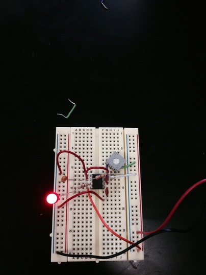
Here is a look at a breadboard with a 555 timer, two capacitors, a potentiometer, an LED light, and multiple resistors.
Reflection
I am not going to lie, at first I had no idea what I was doing at all. When we were given the packet of mini experiments to do using the breadboards, the first thing that went through my mind was that I couldn't do it. While doing many of these experiments, Rachel and I had to continuously ask Mr. Williams and our classmates for help. After a while we finally started to get the hang of it. One thing I learned while doing this project is to not be afraid to ask for help. It turns out I wasn't the only one who didn't understand some concepts. The second thing I learned is that even if something seems complex, if you take it step by step, it really isn't that hard. The first thing that we could have done better was stay on task. the last thing we could have done better was spent more time trying to figure things out ourselves before asking for help. All in all I did end up learning a lot about electricity. Even though Rachel and I didn't understand anything at first we were the first pair to set up the circuit above correctly and make the LED light flash.
